Home / PLC & SCADA programming / Functional design specification guide
Guide · Control system design
How to write a functional design specification for a PLC and SCADA system
What a functional design specification (FDS) is, who writes and approves it, what goes in it, and how it drives the code, the HMI and the testing.
A functional design specification (FDS), also called a functional description (FD) or control philosophy document, describes in plain language how a PLC and SCADA control system will operate the plant. It is the bridge between the process design and the code. A good FDS means the programmer, the client, the operators and the commissioning team all agree on what the system does before anyone writes a line of logic. A poor one, or none at all, is the most common reason control projects run late on site.
This guide is for project engineers, plant engineers and consultants who need to write, review or approve an FDS for a new plant, an upgrade or a PLC and SCADA programming package.
What an FDS is for
- Agreement: it records what the client, process designer and integrator have agreed the system will do
- Design input: it is the specification the PLC code, safety logic and HMI screens are built from
- Test basis: the factory and site acceptance tests are written from it
- Operations record: after handover, it tells operators and maintenance staff how the plant is meant to behave
It is not a code listing, an IO list or an operating manual, though it references all three. It describes behaviour: what happens, when, and why.
Control philosophy, FDS and design specification
Names vary between companies and industries. A common sequence is a short control philosophy written by the process designer or client, setting out the intent; an FDS written by the control system integrator that turns that intent into detailed, testable behaviour; and sometimes a software design specification describing how the code itself is structured. On smaller jobs the control philosophy and FDS are often one document. What matters is that the behaviour is written down and approved before coding starts.
Who writes it and who approves it
The FDS is usually written by the control systems engineer or integrator, with input from the process engineer, the mechanical and electrical designers, the client's operations and maintenance staff and, for regulated plant, the quality team. It is reviewed and approved by the client or their consultant.
Approval should happen before the code is written, and the approved revision should be frozen. Changes after that go through a simple change control: a revision, a reason and agreement on cost and programme. That protects the client as much as the integrator, because every change is visible.
Structure of a good FDS
Most good FDS documents follow a similar outline. The table below is a template you can adapt.
| Section | What it covers |
|---|---|
| 1. Introduction and scope | Purpose, plant area, what is in and out of scope, reference documents, abbreviations |
| 2. Process description | What the plant does, in plain words, with the P&ID or process flow references |
| 3. Control system overview | PLC, safety controller, HMI and SCADA hardware, network architecture, interfaces to other systems |
| 4. General control philosophy | Plant-wide modes, start-up and shutdown, power failure and restart, standard device behaviour, naming conventions |
| 5. Equipment module descriptions | For each module: purpose, devices, modes, permissives, interlocks, sequences, setpoints, alarms |
| 6. Alarms and events | Priorities, alarm list or rules for building it, latching and acknowledgement |
| 7. HMI and SCADA | Screen hierarchy, operator actions, user levels, trends, reports, data historian |
| 8. Communications and IO | Fieldbus and network links, data exchanged with other systems, IO list reference |
| 9. Safety functions | A reference to the safety requirements specification, not a copy of it |
| 10. Testing | How the FAT and SAT will test each section, and the acceptance criteria |
| Appendices | IO list, alarm list, cause and effect charts, setpoint schedule, open questions register |
Writing the equipment module descriptions
The heart of the FDS is the description of each piece of plant. Breaking the plant into modules, the approach used in ISA-88 (IEC 61512) for batch processes and widely copied elsewhere, keeps the document and the code tidy. A module might be a pump set, a tank with its level control, a CIP circuit, a conveyor section or a filler. For each one, describe:
- Purpose and devices: what it does, and the tags of every motor, valve and instrument in it
- Modes: for example auto, manual, maintenance and out of service, and who can change modes
- Permissives: what must be true before it can start
- Interlocks and trips: what stops it, whether it latches and what reset is needed
- Sequences: step by step, with transition conditions, timeouts and what happens on a fault at each step
- Control loops: process variable, setpoint source, output and limits
- Setpoints and parameters: which ones operators can change, and their ranges
- Alarms: each alarm, its trigger, priority and delay
Write sequences so they can be tested. "The pump starts when the tank is full" is vague. "When LT-101 is above 85% for 5 seconds and the outlet valve XV-102 is confirmed open, start P-101" can be tested and ticked off.
Modes, start-up, shutdown and failures
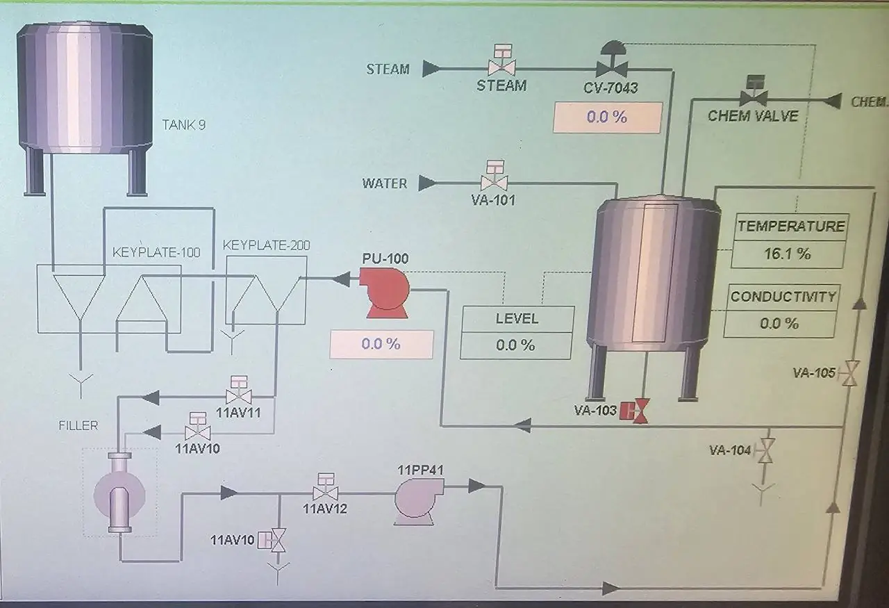
Plant-wide behaviour belongs in the general section so it isn't repeated in every module. Cover power-up and restart after a power failure, controlled shutdown, emergency stop behaviour, loss of communications, failed instruments and what happens when the PLC goes to program mode. The question "what should the plant do when this fails?" is the one most often left out, and the one that causes most surprises at commissioning.
Need an FDS written for your project? We write the functional design specification, then build and commission the system to match. Send us the scope, drawings or a few photos and an engineer will reply within one business day.
Interlocks, HAZOP, CHAZOP and safety functions
Process HAZOP studies produce many of the trips and interlocks the FDS must describe. A control system hazard study (CHAZOP) looks at the control system itself: what happens if a PLC, network, drive or HMI fails, or an operator makes the wrong entry. Recommendations from both should be traceable to clauses in the FDS.
Safety functions are different. Safety-related functions, such as emergency stops, guard interlocking or safety instrumented functions, should be specified in a separate safety requirements specification, written to AS 4024 for machinery or AS IEC 61511 for process safety instrumented systems. The FDS should reference that document and describe how the basic control system responds when a safety function trips, but not try to replace it. See our machine safety service for that side.
HMI and SCADA
Describe the screen hierarchy, the information each screen shows, the actions operators can take, user levels and passwords, trends, reports and data logging. Mock-ups of key screens help clients review early. Define standard faceplates for motors, valves and loops once in the general section, then refer to them.
How the FDS drives the code and the testing
When the FDS is structured by module, the PLC program can follow the same structure, with one routine or add-on instruction per module type. The HMI screens follow the same tags and names. The FAT test sheets are then written straight from the FDS: each permissive, interlock, sequence step and alarm becomes a line to test and sign. The SAT repeats the key tests with real field devices and process. If a test can't be written for a clause, the clause probably needs rewriting.
Common mistakes
- Starting code before approval: the FDS becomes a description of whatever was written, not a specification
- Too vague: words like "normally", "as required" and "appropriate" can't be tested
- Copied from another job: leftover equipment and sequences confuse reviewers and testers
- No failure behaviour: only the happy path is described
- Safety logic mixed in: safety functions described loosely in the FDS instead of a proper safety requirements specification
- Never updated: changes made on site never make it back into the document, so the as-built FDS is wrong at handover
- No operator input: the people who will run the plant see it for the first time at commissioning
A simple process
- Gather inputs. P&IDs, process description, equipment lists, HAZOP actions and the client's standards.
- Agree the structure. Break the plant into modules and agree standard device behaviour.
- Draft and workshop. Walk through each module with process, operations and maintenance staff.
- Review and approve. Close out comments and freeze the revision.
- Code, test and update. Build from it, test against it, and update it to as-built at handover.
How AMC helps
AMC writes functional design specifications for PLC, SCADA and safety systems on new plants and upgrades, and works as an engineering partner to project engineers and consultants who need control system design done properly. Our automation engineers program Allen-Bradley Logix and GuardLogix, Ignition, Citect and Geo SCADA, and our electricians install and commission, so the FDS is written by people who will build and test it. We use it to drive the code, the HMI and the FAT and SAT sheets, as on our CIP and filler control system and in water and wastewater automation work.
This guide is general information. Your organisation, client or industry may have its own document templates and quality requirements, and safety functions must be specified and validated to the applicable standard. Written by the AMC Electrical & Automation engineering team in Griffith, NSW. Last checked November 2026.
FAQs
Common questions about functional design specifications
What is a functional design specification for a control system?
A functional design specification (FDS) describes in plain language how a PLC and SCADA system will control the plant: modes, permissives, interlocks, sequences, alarms and operator screens. It is approved before coding and used as the basis for testing.
What is the difference between a control philosophy and an FDS?
A control philosophy usually sets out the intent of how the plant should be controlled, often written by the process designer or client. The FDS turns that into detailed, testable behaviour for each piece of equipment. On small jobs they are often combined.
Who writes the FDS?
Usually the control system integrator or controls engineer, with input from process, electrical and mechanical designers and the client's operations and maintenance staff. The client or their consultant reviews and approves it.
Should safety functions be in the FDS?
The FDS should reference safety functions and describe how the control system responds to them, but the safety functions themselves belong in a safety requirements specification written to AS 4024 or AS IEC 61511, as applicable.
How detailed should an FDS be?
Detailed enough that a programmer can write the code and a tester can write a pass or fail test for every clause, without guessing. If a sentence can't be tested, it needs more detail.
How does an FDS relate to FAT and SAT?
The factory and site acceptance test sheets are written from the FDS. Each permissive, interlock, sequence step and alarm becomes a test item, so a well-structured FDS makes testing faster and disputes rarer.
Does the FDS need updating after commissioning?
Yes. Any changes agreed during commissioning should be added so the handover FDS matches the as-built system. Otherwise the next upgrade starts from a document that is wrong.
Next step
Got a plant, machine or board that needs sorting?
Send us the scope, drawings or a few photos. An engineer reads every request and comes back within one business day with next steps and a clear, upfront price.
Project engineer or OEM? Send a P&ID, equipment list or scope for a budget price.